Simulation window and grids
Fields and densities grid
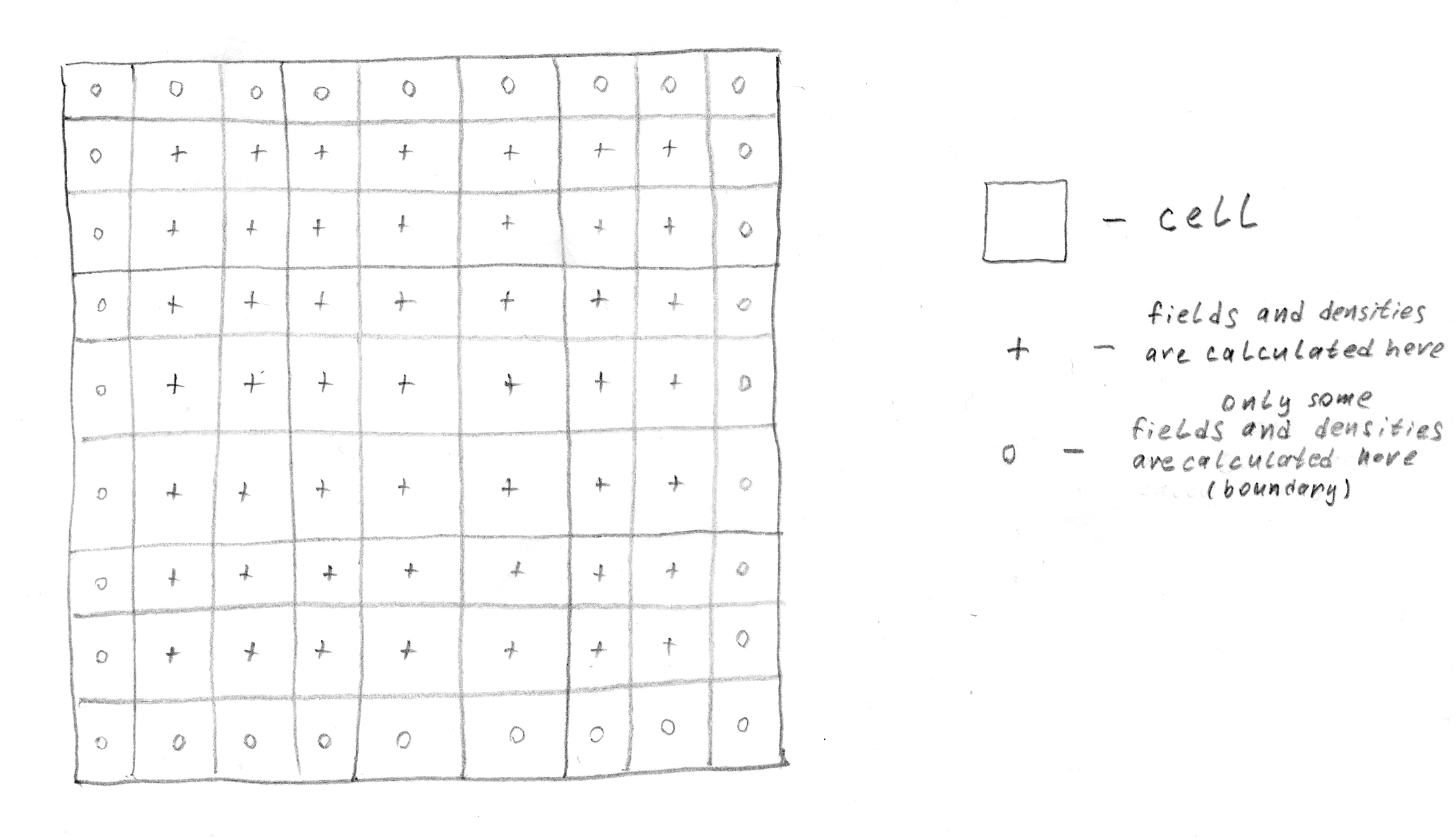
The grid on which the fields and densities are calculated.
Fields and densities (\(ro\), \(j\)) are calculated on a
config.grid_steps x config.grid_steps-sized grid.
This number must be odd in order to have an on-axis cell
for on-axis diagnostics.
-
config_example.grid_steps= 641¶ Transverse grid size in cells
-
config_example.grid_step_size= 0.025¶ Transverse grid step size in plasma units
The fields are calculated at the centers of the grid cells.
Note
The muddy concept of ‘window width’ is no longer referenced in LCODE 3D
to ease up the inevitable confusion about what it actually means
and how it relates to config.grid_step_size.
Please refrain from thinking in these terms
and head over to the following subsection for more useful ones.
Reflect and ‘plasma’ boundaries
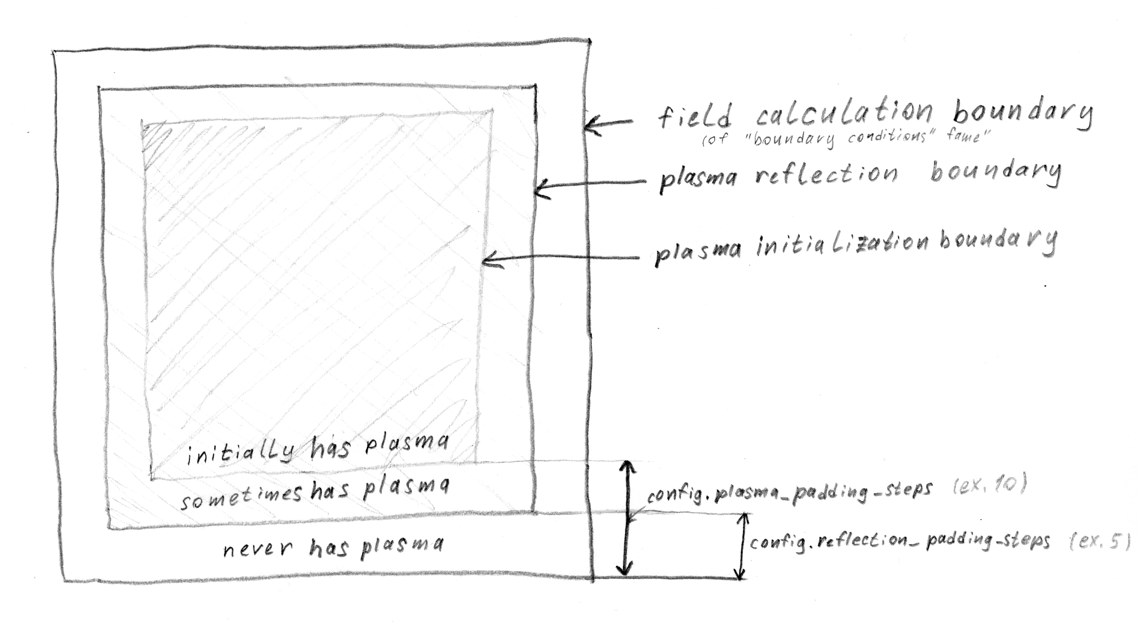
The reflect and plasma boundaries illustrated.
-
config_example.reflect_padding_steps= 5¶ Plasma reflection <-> field calculation boundaries
-
config_example.plasma_padding_steps= 10¶ Plasma placement <-> field calculation boundaries
The plasma partlcles are not allowed to enter the outermost cells
in order to simplify the treatment of boundary regions
during interpolation, deposition and field calculation
[Zero special boundary treatment].
In order to achieve that, the reflection boundary is placed
config.reflection_padding_steps steps deeper into the simulation area.
Note
While choosing the value for this parameter, one should take into account the particle size. Even a single fine [Coarse/fine plasma] particle is three cells wide in deposition, [Plasma], so the gap width should be wide enough to cover the entire coarse particle cloud size. Failure to meet this condition may result in a memory violation error. This could be solved by introducing fine particle reflection, but that’d be more resource-intensive.
Note that while it defines the area where plasma is allowed to be present,
it must be larger than the area where the plasma is initially positioned.
The size of the second area is controlled by the
config.plasma_padding_steps,
which puts a cut-off limit on the placement
of both coarse and fine plasma particles.
Coarse and fine plasma grids
Finally, the plasma boundary hosts two grids of particles, the coarse grid and the fine grid [more info in Coarse/fine plasma approach], which are coarser and finer than the field grid respectively.